
Radio Controlled Rocket Glider Kits
Welcome to the world of rocket boosted radio control gliders. This is not a model for a novice RC pilot, but anyone who is comfortable with RC flying of a medium speed model should be fine. Read through the instructions, look at the photos and be sure you understand the step before commiting to cutting or glue.
Instructions:
Identify all pieces, the kit should contain:
1 wing taped together
2 wing spars(carbon fiber)
2 pushrods
1 Vertical Stabilizers
1 horizontal stab assembly.
2 long Foam wing reinforcing strips
2 medium Foam horizontal tail reinforcing strips
2 short foam motor mount reinforcing strips
2 Body Tubes
2 ramjet intake blocks(foam/ply stacks)
2 ramjet standoffs
2 ramjet tubes
2 servo ez links.
3 3/8" wide foam strips for the conduits.
Motor mount
Velcro(for battery and rx/bec attachment)
2 Rail buttons/t-nuts or 1 Launch lug
3M blenderm tape
Lead weight
Spare depron
Notes before starting:
Reference to CA+ means foam safe CA+, normal CA+ will melt the foam! Normally you need to use accelerator to get the CA to set on the foam since there is nothing for it to soak into and activate.
You may use 220-320 grit sandpaper and a sanding block to slightly round the edges of the foam if you prefer that look. It will not markedly impact the flight performance either way. Be very careful and use a light touch, it is very easy to catch the foam on the edge of the paper and tear the foam. Do any sanding before assembly.
Weight is critical and the model is designed for the thrust and flight loads. Weight in the rear end is bad and will require additional weight in the front of the model. I did not use any epoxy on my model. You may use a very small mount when mounting the ramjet pods to the body tube, but it is not necessary and adds weight.
Assembly:
- Unfold the wing and glue the tape joint using CA+ and accelerator, make sure it is flat
- Glue the two wing spars in the pre-slotted areas on the bottom of the wing with CA+ and then tape over with the included blenderm tape.
- Body Tubes. One of the tubes is longer and has a coupler, that's the front tube, we'll use that later. The other tube will have a line inside the tube on one end, that is the rear tube and the inside line is for the motor tube alignment.
- If using rail buttons, use a tool or drill make holes in the tube at the "x" marked "RB". Insert a T nut into each hole from the inside and then install the rail button and screw. You don't need to tighten them down really tight, just enough to hold them in place
- Insert the two pushrods into the the third hole from the outboard end of the control horns on the horizintal stab assembly. Do this from the inboard side of the horn, do it now because it is difficult to do this once the stab is glued to the tube. You will need to twist the pushrod to get it to go into the hole, be careful and don't poke your finger, go slowly so that it fits snugly.
- Glue the horizontal stab assembly to the top of the rear body tube with the rear of the stab flush with the end of the tube. Use the alignment line on the tube to make sure it is straight.
- Glue the motor tube at the top of the body tube right underneath the horizontal stab and aligned with the end of the body tube. Use the alignment lines on the body tube and motor mount. The model is upside down now so it will be the at the bottom of the tube in this orientation. Make sure the motor tube is aligned straight with the body tube. There are no centering rings needed or desired because you may need to reach wiring or weight at the rear of the model. The motor tube hook is only taped on one side, you want to be sure you don't glue to the tape or hook, this is done so that you can glue the paper motor tube directly to the body tube without the tape in the way.
- Glue the two
short reinforcing strips on either side of the motor tube and add a fillet of CA+ to help support the motor tube.
- Glue the two medium reinforcing strips on either side of the horizontal stab/body tube joint and add a small CA fillet. This provides extra strength for the joint. Don't push the strips in too hard or it can rotate the tube slightly.
- Cut a rectangle in both sides of the body tube for your servos. Make sure you mount them so that the servo wire is facing forward. Plan the location of the servo arm and leave enough space that your pushrod will be able to be adjusted forward or backward with the ez connector and not be too short. Note the servo output arms face up so that the pushrod will be fairly straight to the stabilator control horn. I used the small servo screws straight into the cardboard tube for mounting my servos. I then reinforced the holes with CA glue and reinstalled them. You can also put a small balsa block(not included) inside the tube on each end of the servo cutout to mount the screws into. Use the ez links to connect the pushrod to the servo output arms. Attach a 24" servo extension to each servo lead to allow you to reach the receiver at the front of the model. Remove the servos for the rest of the assembly.
- Glue the front body tube to the rear assembly, making sure to keep the line on the top of the tubes aligned, this is used to align the wing and conduits and to keep the ramjet pod holes aligned..
- Make a line 1.5" in front of the LE of the horizontal stabilizer. This will be the TE of the wing.
- Lay the wing upside down on a flat surface. Using CA+ foam safe glue, glue the body tube to the wing. Use the pencil marks on the body tube as a guide to keep it straight. Make sure the rear of the wing is 1.5" forward of the front of the horizontal stabilizer assembly.
Apply CA+ foam safe glue to one of the reinforcing strips and glue one on each side of the wing/body tube joint. This piece is there to give more gluing surface to the wing/body tube. If you push in too hard on these strips it can cause the body tube to rotate slightly, so pay attention. Once they are in place put a fillet of CA+ on both the wing and body tube joints. - Glue a standoff to each ramjet tube using the holes provided, try to keep the standoff perpendicular to the tube. If you can get some glue inside the tube onto the carbon rods that helps to reinforce them. If you use epoxy use a very small amount, as weight is critical in this model.
- Glue a ply/foam disk stack into the front of each ramjet tube. The ply plate will not be inside the body tube but flush with the front.
- Using the template provided in the pictures above print out the ramjet cones full size without any scaling. Roll the paper over a table top to curve it and then glue the tab to make a cone. Reinforce the inside and outside with CA glue to harden it and then glue to the ply disk. This is the lightest alternative. You can also use balsa or a dowell to make two ramjet cones using a drill press or belt sander and glue them to the front of the ply disks, they can be anywhere from .5 -.7 diameter and 1-1.25" long. Or you can use bnc-20y cones available from BMS or Semroc/E-rockets and cut off the shoulder or get the PNC-20 pack from Estes which includes two pnc-20y cones and cut off the shoulder of those, or order them from Sirrius:
- Glue each ramjet pod into the fuse using the holes provided. If you use epoxy, use a very small amount as weight is critical in this model.
- Glue the vertical stab to the horizontal stab using the tab. Make sure it is 90 degrees to the wing, is straight and reinforce with a slight fillet.
- Cut a strip of conduit to fit between the TE of the wing and the front of the stab. Glue it in place.
- Cut a strip to go from the front of the the wing to the front of the body tube. You will need to sand/cut the front to a pointed shape.
- Using the two remaining strips cut/fit them to to the top of the conduit strip and the top of the wing. The front and rear should be sanded/cut to a pointed shape. Carefully sand the top of these conduit pieces round then glue them in place. It's hard to sand them to a rounded shape after gluing them in place. Take your time.
- Re-install your servos. Route the servo wires to the front of the body tube. Attach them to the receiver.
The basic construction is now complete.
Radio Installation
Note: Your radio needs to be configured for Delta mixing, this means that the servo arms will move the same direction during elevator stick movement and opposite for aileron stick movement. Connect your servos to the receiver one in the aileron connection and one on the elevator connection and apply power. Use a servo arm at least 9/16” long and with holes small enough that there won’t be slop with the pushrod wire when installed. I use the hole furthest out on the servo arm, to maximize movement. On some servos there are a long two-ended servo arm, you can trim off one end if needed to get sufficient length. Zero out any trim settings on the transmitter.
- Connect a servo to each pushrod using the ez connector. Flip the model right side up and look at it from the rear. Moving the transmitter stick back(up elevator) should move both elevons up. Moving the transmitter stick to the right should move the right elevon up and the left elevon down. If you can’t get the servo reversing to give you the right polarity try swapping aileron/elevator inputs to the receiver. If that is correct, continue..
- Make sure the control surfaces are centered, use the ez connector to adjust if needed. Now measure the control surface movement. Full elevator and aileron movement should be 1.5-1.75” in each direction. Since the model will be nose heavy, extra elevator movement helps to give sufficient authority during glide. For boost, due to the extra throw it may be twitchy, you can consider dual rate for boost to help tone this down.
- If you have a flap/elevator mix you can program up elevator to a switch setting. The model needs approximately 5/8” of up elevon during glide. If you can’t set the up elevator trim to a switch on your radio you’ll have to manually put in boost and glide trim which is hard to do while flying the model.
- Use the included Velcro to attach
the receiver 1.5" from the front of the body tube. This allows you to be able to remove and replace the receiver if needed for repairs or for removing the servo wires. I attached the battery inside the body tube at the front next to the receiver.
- Insert your heaviest loaded rocket motor into the motor mount
- Support the model at the balance point indicated for boost. I use two pencils with the eraser pointed up and held in place with a small hand vice. Place the model rightside up on the pencil erasers on the balance point indicated in the kit spec sheet. Use the included lead weight as needed and as far forward in the end of the nose cone as possible to balance it. You can secure the weight with CA or a small dab of epoxy to hold it in place.
- Do not try to fly the model with it balancing it behind this point. The adage is, a nose heavy model flies poorly, a tail heavy model flies once.
- I covered my ramjet tubes in self adhesive monokote trim/vinyl to help protect against water and landing damage to the tubes, I suggest doing the same.
- If you paint the model, make sure you test it on scrap foam first.
- If you are going to paint the model, you can mask off the servos. Make sure no paint will get on the servo output arm. Make sure to test the paint on a scrap piece first to ensure it won’t melt the foam. I use Model Master(testors) or testors small rattle cans for painting directly on the foam.
- I used vinyl for the trim colors on my model. With the vinyl from stickershock23 it helps once applied to use a hair dryer on hot to soften the material and then push it down onto the model with a towel. It helps it confirm and stick much better, especially on painted surfaces.
- Use a black sharpie to add panel lines if desired.
- Once you have finished your model: Using a tool, make two holes into the front bottom of each ramjet pod for the plastic two pronged skids. These help protect the ramjets when landing. You want the front of the skid to be even with the front of the ply plate. The prongs should go through the ramjet tube and glue into the foam stack. Glue them in place. Trim all but 1/16" of the skid off. If you leave the complete skid it puts more stress on the ramjet pod on landing.
- Re-install the receiver and battery
Flying: See the Instruction/Information link at the top for flying instructions Be ready on the first few flights to keep the model straight till you have the trims set perfectly for boost and glide.
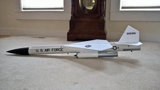
These kits are for the advanced rc rocket glider flyer. Wing loading and weight is higher than my other kits. If your RTF weight is near 15 oz, you can successfully boost/fly it on E-6 torkcet motors. If it is heavier, it requires it to be boosted on a faster E-12RC or E-15-PW aerotech motor, or an epoxy plugged Estes E-12-0. The landing on the ramjet pods requires more finesse on landing to avoid damage to the model. Glide times are correspondingly shorter, typically around 30 seconds. It is 45" long, 2.6" diameter, ~16 oz rtf and has a 21" wingspan. It is approximately the same size as the madcow kit but approximately 1/3 of the rtf weight. At this time I only have parts for one more kit.
Please refer to the notes on items needed for completion and flying, then read the instructions completely before starting assembly. The assembly photos are for general reference but may not include every step in the manual.
CG location for rocket flight 9 3/16" forward from the TE of the wing
Copyright © dynasoarrocketry.com. All rights reserved.
