
Radio Controlled Rocket Glider Kits
Welcome to the world of rocket boosted radio control gliders. This is not a model for a novice RC pilot, but anyone who is comfortable with RC flying of a medium speed model should be fine. This model has a very moderate glide and slow landing speed. Read through the instructions, look at the photos and be sure you understand the step before commiting to cutting or glue.
Lifting body Rocket glider instructions
Identify all pieces, the kit should contain:
1 lifting body wing taped together
2 pushrods
2 Vertical stabs
Upper fuselage side view taped together
Lower fuselage side view taped together
Motor mount
Velcro(for battery and rx/bec attachment)
2 Rail buttons(2 washers, 2 collars, 2 screws, 2 plastic plugs) or 1 Launch lug and styrene strip
3M blenderm tape
1 Short and 2 long carbon wing spars.
Lead weight
Spare depron
Optional(if ordered):
Electric motor adapter
Notes before starting:
Reference to CA+ means foam safe CA+, normal CA+ will melt the foam! Normally you need to use accelerator to get the CA to set on the foam since there is nothing for it to soak into and activate.
You may use 320 grit sandpaper and a sanding block to slightly round the edges of the foam if you prefer that look. It will not markedly impact the flight performance either way. Be very careful and use a light touch, it is very easy to catch the foam on the edge of the paper and tear the foam.
Epoxy is not needed in this model. Weight is critical and the model is designed for the thrust and flight loads. Weight in the rear end is bad and will require additional weight in the front of the model.
These instructions are valid for all three versions of the lifting body kit. Only the shapes of the body and wing tips are different. The X-24A style and HL-10 Style wingtips will angle outward slightly, the X-20 style are vertical.
Assembly:
- Unfold the lifting body wing and glue the tape joints using CA+ and accelerator, make sure it is flat.
- Test fit, then glue the three spars in place in the slot on the bottom of the wing. Tape over the spars with blenderm tape once the glue has set.
- Unfold the fuselage side view top and glue it at the tape joint, tape the other side of the joint when the glue has set.
- Unfold the fuselage side view bottom and glue it at the tape joint. Apply blenderm tape to the joint on the other side when the glue has set.
- Glue the fuselage bottom side view piece(keel) in place, make sure it is straight and centered and lined up with the front of the wing and the motor mount cutout. Apply a fillet of CA+ to both sides. Note that on the X-24 style and HL-10 style the more blunt rounded end is the front of the keel, on the X-20 style the end with the longer tapered end is the front. This isn't critical, it's just a visual thing, you can always sand the front or rear to any shape you want after it is installed or if you get it backwards.
- Flip the wing over and lay one half on the edge of a table, using a weight to keep it in place.
- Test fit the top side view fuselage into the top of the wing, be careful to not break off the tabs, The foam compresses slightly so it is ok to press them in place. Once aligned perpendicular to the wing and ensuring it is straight with a straight edge, apply a bead of CA+ to both sides of the joint.
- Test fit the motor mount in place and glue with CA+. Make sure the rear of the fin is straight and glued to the motor mount. Do not use epoxy for this step, it is not needed and you don’t want extra weight at the rear of the model.
- Test fit the vertical stabilizer pieces. They should glue in place on both wingtips and be even with the rear of the wing. The wing tips are pre-sanded at an angle, the angle is not critical, as long as the wing tips are approximately the same and angled out slightly. Make sure the vertical stab is even with the bottom of the wing and glue in place with CA+ on each side. Once dry sand the wing tip joint round on the bottom and round the gusset on the top of the wing as you wish to give it a pleasing shape.
- Install the launch lug or rail buttons:
- Use the included plastic plugs to mount the rail buttons. Make a starter hole with a screwdriver or similar round tool that is slightly undersized, and push the plastic plug into the keel. Try to keep it centered and straight, put a bit of CA+ underneath the plastic head before you push it all the way in. Use a screw, a plastic collar and a plastic washer to complete the rail button guide. You'll need to keep the collar centered when assembling as the screw is slightly undersized for the hole in the collar. Put the rail buttons about 10" apart on the keel. Install the wing guard nylon pieces in front of each rail button. Make sure they are lined up with the rail buttons so that they do not bind on the rail. These guards help prevent damage to the rail buttons when landing on hard surfaces. If you land on grass you may omit these.
- If you have an older kit with styrene strips and one piece rail buttons follow the below instructions:Use CA+ to glue the styrene strip on the bottom of the bottom side view fuselage piece, centered between the two black lines. Have the dots facing up. This will reinforce the bottom of the fuse where the rail buttons will mount. Drill a small starter hole for each rail button screw in the styrene about an inch from each end(the dots mark approx. location) and screw in your rail buttons.
- If you will be landing on a rough surface, you may install the wing guard nylon pieces in front of and behind the rail buttons, glue this into the foam, not the styrene strip. Make sure they are lined up with the rail buttons and that they do not bind on the rail.
- If you have an older kit with styrene strips and one piece rail buttons follow the below instructions:Use CA+ to glue the styrene strip on the bottom of the bottom side view fuselage piece, centered between the two black lines. Have the dots facing up. This will reinforce the bottom of the fuse where the rail buttons will mount. Drill a small starter hole for each rail button screw in the styrene about an inch from each end(the dots mark approx. location) and screw in your rail buttons.
- If using a launch lug, glue it to the middle of the styrene strip using CA, then glue the assembly to the side of the keel of the model Just make sure the rod will clear the motor mount and any electronics.
The basic construction is now complete.
Radio Installation
Note: Your radio needs to be configured for Delta mixing, this means that the servo arms will move the same direction during elevator stick movement and opposite for aileron stick movement. Connect your servos to the receiver one in the aileron connection and one on the elevator connection and apply power. Use a servo arm at least 9/16” long and with holes small enough that there won’t be slop with the pushrod wire when installed. I use the hole furthest out on the servo arm, to maximize movement. On some servos there are a long two-ended servo arm, you can trim off one end if needed to get sufficient length. Zero out any trim settings on the transmitter. The model once the motor has burned out is nose heavy and flying wings lose pitch authority when nose heavy so you want as much up elevator travel for trim/flare as possible.
- Install a pushrod in the outermost hole of each control surface control horn. The pushrod should toward the fuselage side of the control horn. You may need to twist the wire back and forth to get it to go into the hole, it should be snug and slop free. It may be necessary to rotate the pushrod end to drill the hole large enough to fit, be careful not to puncture your finger. Be careful to support the control horn so that you do not break the glue joint in the control surface. It is snug but it will fit with patience.
- Install the other end of the pushrod to the servo output arm, again making sure the servo wire is toward the fuselage side of the model. If the wire is too tight, you can use twist an exacto knife in the servo arm hole to make it larger, but be careful and do not make it too large. Once connected, tape each servo in place so that the control surfaces are centered. Flip the model right side up and look at it from the rear. Moving the transmitter stick back(up elevator) should move both elevens up. Moving the transmitter stick to the right should move the right elevon up and the left elevon down. If you can’t get the servo reversing to give you the right polarity try swapping aileron/elevator inputs to the receiver or turning the servos over and swapping the servo arms to the other side of the output shaft. If that is correct, continue.
- Flip the model upside down and supported. The servos may be attached to the model using double back servo mounting tape(not included) or by directly gluing the servo to the wing with CA+ or a small amount of epoxy. Double back servo tape can loosen over time and with exposure to heat, I prefer to glue the servo in place. With the radio still on, put a small amount of glue on the servo, being careful not to get any near the output shaft. And set it in place on the model keeping the control surface centered. Do the same to the other side. Make sure the glue is set before continuing.
- Flip the model back right side up. Make sure the control surfaces are centered, use trims if needed. Now measure the control surface movement. Full elevator movement should be ½” to ¾” in each direction. Aileron movement should be about 70% of the elevator movement. With modern radios you can typically set these movements. Since the model will be nose heavy, extra elevon movement helps to give sufficient authority during glide.
- If you have a flap/elevator mix you can program up elevator to a switch setting. The model needs approximately 1/8” of up elevon during glide. Boost will use completely neutral elevon settings. If you can’t set the up elevator to a switch on your radio you’ll have to manually put in glide trim which is hard to do while flying the model.
- Once complete you can tape the servo wires to the wing using the blenderm tape. Use the included Velcro to attach the receiver and battery to the model as far forward as practical. This allows you to be able to remove and replace the receiver if needed for repairs or for painting..
- Insert your heaviest loaded rocket motor into the motor mount
- Support the model at the balance point indicated for boost. I use two pencils with the eraser pointed up and held in place with a small hand vice. Place the model upside down on the pencil erasers on the balance point indicated in the kit spec sheet.
- Do not try to fly the model with it balancing it behind this point. The adage is, a nose heavy model flies poorly, a tail heavy model flies once.
- If you paint the model, make sure you test it on scrap foam first.
- If you are going to paint the model, you can remove the receiver/bec and mask off the servos and Velcro strips on the model. Make sure no paint will get on the servo output arm. Make sure to test the paint on a scrap piece first to ensure it won’t melt the foam. I use Model Master(testors) or testors small rattle cans for painting directly on the foam. Model master flat black is perfect.
- Use a black sharpie to add panel lines if desired.
- Re-install the receiver and battery
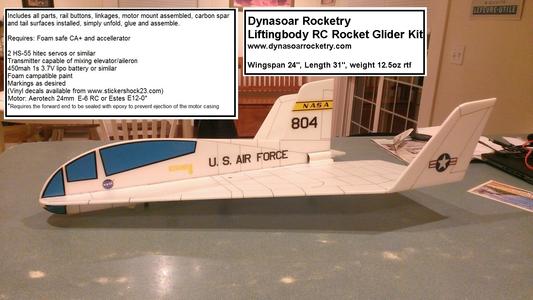
Lifting Body HL-10 Rocket Glider Kit
The lifting body kit is styed after actual lifting bodies from the 1960's. Instead of having normal winged surfaces which can over-heat during re-entry, these used the shape of the body to create sufficient lift to provide a controlled landing on a runway. Decent rate and angle were quite high, just like the space shuttle. These kits use a flat plate wing to simulate the body which gives them the look of the lifting body but a very light wing loading and easy to fly, gentle glide/landing characteristic.
Please refer to the notes on items needed for completion and flying, then read the instructions completely before starting assembly. The assembly photos are for general reference but may not include every step in the manual.
CG location for rocket flight 11 7/8" from the back or nozzle end of the motor mount tube, see the picture below..
(The electric flight adapter is not recommended for this model due to elevon/servo placement interfering with the propellor.)
Copyright © dynasoarrocketry.com. All rights reserved.
