
Radio Controlled Rocket Glider Kits
Orbital Pegasus Rocket Glider Kit
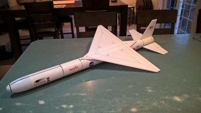
The Orbital Pegasus RC Rocket glider kit is modeled after the air launched sattelite delivery vehcle. It features a clipped delta wing, and full flying tail surfaces. It comes with a plastic nose cone, 2.6" white tubing for the body and depron wing and tail surfaces. Construction is very simple and takes about two hours. You will need two 10 gram type servos, two 24" servo extensions, a receiver, and a small 500mah single cell lipo battery. You will need a transmitter with delta or elevon mixing.
Please refer to the notes on items needed for completion and flying, then read the instructions completely before starting assembly. The assembly photos are for general reference but may not include every step in the instructions. If you want hardcopy to work from, all you have to do is click/drag/select and copy all of the text below the photos, open word and paste with "keep original format" and it looks exactly like it does online then you can print it.
CG location for rocket flight: 16" forward of the rear end of the body tube.
Welcome to the world of rocket boosted radio control gliders. This is not a model for a novice RC pilot, but anyone who is comfortable with RC flying of a medium speed model should be fine. Read through the instructions, look at the photos and be sure you understand the step before commiting to cutting or glue.
Orbital Pegasus Rocket glider instructions
Identify all pieces, the kit should contain:
1 wing
1 Nose Cone
2 pushrods
2 tail surfaces
1 vertical stab
1 carbon pivot rod with small ring glued on one end and spare ring stored on the rod, don't lose this!
2 foam reinforcing strips
2 ez connectors.
2 Centering rings
2 Body Tubes
Motor mount
Velcro(for battery and rx/bec attachment)
2 Rail buttons with t nuts/screws
2 landing skids
Lead weight
Spare depron
Notes before starting:
Reference to CA+ means foam safe CA+, normal CA+ will melt the foam! Normally you need to use accelerator to get the CA to set on the foam since there is nothing for it to soak into and activate.
You may use 220-320 grit sandpaper and a sanding block to slightly round the edges of the foam if you prefer that look. It will not markedly impact the flight performance either way. Be very careful and use a light touch, it is very easy to catch the foam on the edge of the paper and tear the foam. Do any sanding before assembly.
Epoxy is not needed in this model. Weight is critical and the model is designed for the thrust and flight loads. Weight in the rear end is bad and will require additional weight in the front of the model.
Assembly:
- Body Tubes. One tube will have a coupler glued in place, that is the rear tube. Glue the front tube onto the coupler, make sure the small arrow marks are aligned on the two tubes, that will ensure the wing mark and rail button marks are properly aligned. Use CA+ sparingly.
- Glue the two centering rings on the motor mount. The mount is marked for the two rings, and the rings have a notch cut to clear the motor hook, and notches to clear the vertical fin tab, keep the fin tab notches aligned. If not you can always trim them later to fit. Note the front of the motor mount has the ring closest to the end.
- Unfold the front and back wing extensions and glue them with foam safe CA+ so that they lay flat.
- Lightly sand the wing line on the body tube to help adhesion of the glue.
- Insert the pivot rod temporarily into the rear of the body tube through the pre-installed torque tube. This will be used to make sure the wing and tail surfaces are level when gluing the wing in place.
- I sanded the edges of my wing at an angle to give that faceted look, or you can round them if desired before gluing in place. Apply foam safe CA+ onto the wing line and also down the center line of the underside of the wing. The underside has the spar visible.
- Attach the wing onto the body tube keeping it straight and keeping the wing aligned with the front and rear location marks. You can use a little bit of tape to hold the wing in place in the front and back so it doesn't slide forward/backward. Then quickly flip the wing/body over onto a flat surface. Use the pivot rod at the rear by measuring the left and right distance from the rod to the table. Rotate the body tube slightly as needed to get the distance from the rod to the table the same. Be sure you are still keeping the wing straight down the body tube and aligned with the front and rear marks. This ensures that the tail surfaces will be straight with the wing.
- Put a light fillet of CA in the wing/body tube joint once the glue has set and you have made sure the wing is in the correct position and straight.
- Glue the two reinforcing strips on either side of the wing, against the body tube and the wing. Don't push this in too hard as it can rotate the body tube relative to the wing. All this piece does is to act as a filler to allow you to put additional CA fillets against the wing and body tube to help it attach firmly.
- Glue the vertical fin into the slot in the rear tube. Make sure it is straight and perpendicular to the wing.
- Make a hole and insert a T-nut into each pre-marked RB(rail button) location on the bottom of the body tube and then screw in the rail button with the included screw.
- Glue the motor mount into the rear of the model, the motor mount will butt against the torque tube inside the body tube and the notch will slide over the vertical fin tab. You don't need a lot of glue here, just enough to keep it from falling out, the aluminum tube will keep it from moving forward.
- Mount a skid in front of each rail button. Make two starter holes, make sure the skid is not too far forward to interfere with the nose cone shoulder and does not hit the rail button. Make sure they are aligned with the rail buttons. Glue in place with CA+. The skids should fit into the slot in the rail and not drag, and should contact the ground before the rail button to protect them on landing.
- Insert a pushrod rod into the third hole from the furthest out end of each stabilizer horn. Insert the z bend from the inside closest to the body tube so that the wire will be next to the body tube and won't hit the control surface when it moves.
- There is a small aluminum ring shipped on the torque rod that is used to secure the control surfaces. One is glued in place. Remove the second ring and set it aside. Push the carbon pivot rod through one control surface and through the pivot tube in the body and through the second control surface. Make sure the pushrods are installed and the control surface horns are pointing toward the bottom of the model. Install the second little ring on the end of the pivot rod and make sure the surfaces don't have any gaps but can move easily. VERY CAREFULLY apply a very small amount of foam safe CA+ onto the outer end of the pivot rod and aluminum ring and hit it with accelerator to lock it in place. Be very careful not to wick any ca into the pivot tube in the control surface. You get one chance to do this right so take your time. Make sure the surfaces move freely.
The basic construction is now complete.
Radio Installation
Note: Your radio needs to be configured for Delta mixing, this means that the servo arms will move the same direction during elevator stick movement and opposite for aileron stick movement. Connect your servos to the receiver one in the aileron connection and one on the elevator connection and apply power. Use a servo arm at least 9/16” long Zero out any trim settings on the transmitter.
- Cut out the pockets in the body tube for your servos in the approx location marked. Make sure to measure your servos and cut the pocket so that the servo fits snugly in place. Attach a 24" servo extension to each servo.You just need to be able to route the wire to the front of the tube to attach it to the receiver. Route them into the servo pocket in the body tube toward the front and install the servos. Install the servos so that the electrical wire points forward. I used the included screws with my servos to hold them in place in the tube as well as putting a small fillet of CA+ on each side of the servo/body tube joint once installation was complete.
- Install the ez link into the furthest out hole in your servo arm and center your servo arms if needed with the transmitter.
- Use the included ez links to attach the pushrod to your servo, so that the control surfaces are aligned with the wing. The rods are pre-bent for an approx straight line to the servo horn with an ez link installed. If the rod sticks out too far you can bend the angle bends to adjust as needed for a nice straight alignment. If you don't like the ez links you can put z bends on the wires once your servo horns are installed and centered.
- Moving the transmitter stick back(up elevator) should move both stabilizers trailing edges up. Moving the transmitter stick to the right should move the right stabilizer trailing edge up and the left down. If you can’t get the servo reversing to give you the right polarity try swapping aileron/elevator inputs to the receiver If that is correct, continue.
- Make sure the control surfaces are centered, use trims if needed. Now measure the control surface movement. Full elevator movement should be 1.25” in each direction, aileron movement should be 1" in either direction. Since the model will be nose heavy, extra elevon movement helps to give sufficient authority during glide.
- If you have a flap/elevator mix you can program up elevator to a switch setting. The model needs approximately 3/8" to 7/16" of up elevon during glide. If you can’t set the up elevator trim to a switch on your radio you’ll have to manually put in boost and glide trim which is hard to do while flying the model.
- Use the included Velcro to attach the receiver in the nose cone. This allows you to be able to remove and replace the receiver if needed for repairs or for removing the servo wires. I also attached the battery as far forward inside the nose cone as possible using the rest of the velcro
- Insert your heaviest loaded rocket motor into the motor mount
- Support the model at the balance point indicated for boost. I use two pencils with the eraser pointed up and held in place with a small hand vice. Place the model on the pencil erasers on the balance point indicated above. Use the included lead weight to balance it. Do not try to fly the model with it balancing it behind this point. The adage is, a nose heavy model flies poorly, a tail heavy model flies once
- I used decals from Stickershock23 to finish it. With the vinyl from stickershock23 it helps once applied to use a hair dryer on hot to soften the material and then push it down onto the model with a towel. It helps it conform and stick much better.
- Use a black sharpie to add panel lines if desired
- Re-install the receiver and battery
Flying: See the Instruction/Information link at the top for flying instructions. Be ready on the first few flights to keep the model straight till you have the trims set perfectly for boost and glide.
Copyright © dynasoarrocketry.com. All rights reserved.
